UG

UG, UGN
View X rotated by 90°

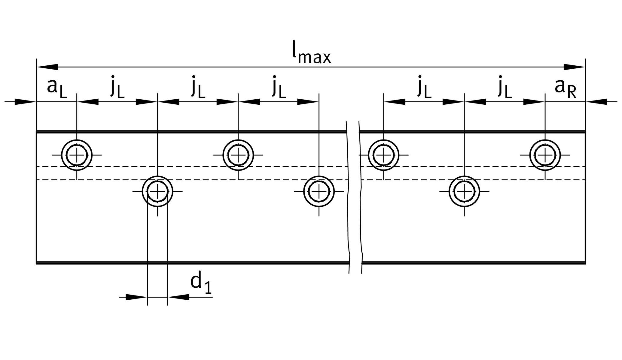
Hole patterns
When ordering, state hole pattern and end spacings aR, aL


| lmin | 70 mm | Length minimum |
| lmax | 2.000 mm | Length maximum 1 |
| B | 66 mm | Width |
| Tol B | -0,1 | Tolerance |
| H | 28 mm | Height |
| Tol H | -0,1 | Tolerance |
| jB | 18 mm | |
| jB2 | 12 mm | |
| jL | 40 mm | |
| aR min | 15 mm | 2 |
| aR max | 35 mm | 2 |
| aL min | 15 mm | 2 |
| a | 35 mm | 2 |
| h1 | 16,5 mm | |
| A2 max | 28 mm | |
| N2 | 15 mm | |
| K1 | M8 | Fixing srews (DIN ISO 4762-12.9) |
| K1 MA | 41 Nm | Torques fixing screws 3 |
| d1 | 10 mm | Bore diameter |
KVK15 | Suitable closing plug 4 | |
RUS19069, RUS19105, RUSV30069-KS, RUSV30105-KS, PR14032, PR14044 | Suitable linear roller bearing 5 |
Footnotes
Maximum length of single-piece guideways; longer guideways are supplied as several segments.
Indicate hole pattern and end spacings aR, aL when ordering.
The stated torques represent maximum values for the secure transmission of forces in vibration-free, quasistatic applications (S0 = 1). We recommend that the tightening torques for the screw connection of the adjacent construction should be determined at the customer under the conditions specific to the application and operation, observing the information in VDI Guideline 2230 Part 1 (2015) and the information in this description.
Closing plugs must be ordered separately.
Linear roller bearings.
| Size code | 6628 | |
| Hole pattern of guideways | BR | Hole pattern on right side |
| Quality grade of guideways | Q6 | Requirements of precision table guidance systems in machine tool construction |
We are sorry...
There is currently no CAD file available for this product. If you’d like to be notified when CAD is available, sign in or register for free.


